3.3. Actions with Model
The DICOM Viewer allows you to perform the following actions with a model:
-
Pan leftward and rightward using the

 keys.
keys.
-
Zoom the 3D image by rolling the mouse wheel or using the

 keys.
keys.
-
Rotate by moving the mouse holding the wheel or using the Rotate tool (see Section 3.4.2).
On the left side of the window, there is a panel of standard spatial orientations of the model (Fig. 3.4). To quickly switch to a specific spatial orientation of the model, click the corresponding button on the panel. To open additional orientation options for the LAO and RAO buttons, click the arrow on the button. The action of the panel buttons applies only to the window in which the panel is located.
To set the orientation angles manually, click the Set orientation angles  button (for
details, see Section 3.3.1).
button (for
details, see Section 3.3.1).

The panel with space orientation selection buttons (Fig. 3.4) is available in the Volume reconstruction and 3D view windows of the MPR reconstruction, Vessel analysis and Coronary artery analysis tabs. You can set the visibility of the standard space orientation panel in the UI tab. To do that, go to the 3D reconstruction and Vessel analysis module settings (see Sections 16.7.3 and 16.7.4).
3.3.1 Setting the model orientation angles
____________________________________________________________________________________________
Functionality is available in the Pro edition
____________________________________________________________________________________________
To set the orientation angles manually, click the Set orientation angles button on the
panel of standard spatial orientations of the model on the left side of the window. The dialog box for
setting orientation angles will open (Fig. 3.5).
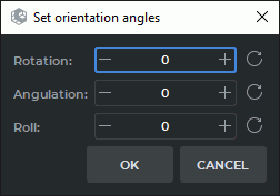
In the dialog box for setting orientation angles (Fig. 3.5), specify the angle values in the Rotation, Angulation, and Roll fields. Angle values must be specified only in whole degrees.
When entering values, consider the following specifics:
-
the Rotation and Roll fields are cyclic. The value 180° is followed by -179°, and the value before -179° is 180°;
-
next to each field there is a Reset angle
 button, which resets the corresponding
angle value to 0;
button, which resets the corresponding
angle value to 0;
-
angle changes are applied immediately after a new value is entered;
-
clicking the CANCEL button restores the angle values that were set before the dialog box was opened.
When the Angulation angle value reaches +90° or -90°, the Roll value is automatically reset to 0 and becomes unavailable for editing. The Roll value is transferred to Rotation using the formula Rotation = Rotation + Roll.
The angle values are displayed in the lower-right corner of the window with the volume model (for details, see Section 3.3.2).
 | When transferring angles to an angiograph, the resulting projection may differ from the projection in DICOM Viewer if a different center of rotation of the model was used. |
| | If the Roll value is not zero, the projection on the angiograph may not match the projection in DICOM Viewer, because angiographs usually do not support a third axis of rotation. |
3.3.2 Displaying model orientation angles
____________________________________________________________________________________________
Functionality is available in the Pro edition
____________________________________________________________________________________________
DICOM Viewer allows you to display the orientation angles of the volume model. This functionality is intended for assessing the current spatial orientation of the model and quickly switching to a specified projection.
To display or hide the angles, click the arrow next to the Show labels  button and select or
clear the Show orientation angles check box. By default, the display of orientation angles is
disabled.
button and select or
clear the Show orientation angles check box. By default, the display of orientation angles is
disabled.
The angle values are displayed in the lower-right corner of the window with the volume model. Angles are displayed with precision to whole degrees.
The angles correspond to the following rotation order:
-
Rotation — rotation about the Z axis;
-
Angulation — rotation about the X axis;
-
Roll — rotation about the Y axis.
The rotation order corresponds to the ZXY Euler angles. The AP position (front view) corresponds to the values Rotation = 0, Angulation = 0, Roll = 0.
The angles are displayed in the following format:
-
Rot.: RAO X° or Rot.: LAO X°. At a zero value, Rot.: RAO 0° is displayed;
-
Ang.: Cran X° or Ang.: Caud X°. At a zero value, Ang.: Cran 0° is displayed;
-
Roll: Ant X° or Roll: Post X°. At a zero value, Roll: Ant 0° is displayed.